Borjibot
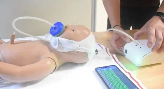
A soft robotic device, custom-designed for the oral rehabilitation of newborns. IEEE BioRob 2020.
Borjibot is a soft robotic device developed in 2019 through a joint research project between the Instituto Nacional de Salud del Niño San Borja and the Universidad Privada Cayetano Heredia, custom-designed for the oral rehabilitation of newborns.
Objective
- Create a robotic device with soft actuators capable of stimulating the facial muscles of newborn babies, mainly premature babies.
Impact
Rehabilitating the facial muscles helps babies recover their swallowing reflex. Without this reflex, a premature baby’s chances of survival drop sharply.
The shortage of staff specialized in this rehabilitation means that many newborns do not receive the care that would give them a better chance of feeding and surviving. A robotic device would expand a rehabilitation specialist’s ability to care for more newborns.
Contribution
My role in the project was to develop the design and engineering needed to build a working prototype that could be used for the biomedical validation phases. During development it also became necessary to design a bench to characterize the soft actuators used in the prototype, so I took charge of that device as well.
Development of the facial device
During the first meetings with the medical team of the Instituto Nacional de Salud del Niño San Borja, led by Dr. Cruz, and the biomedical engineering team of the Universidad Privada Cayetano Heredia, led by PhD. Vela, the principles for developing the device were established. Since my role on this team was design and construction, I focused on gathering the needs and technical requirements.
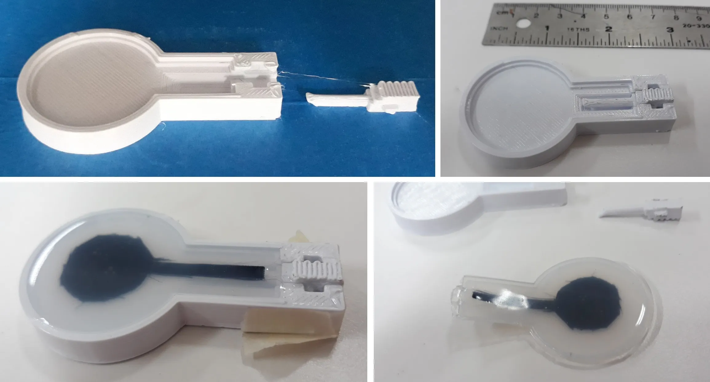
After researching the state of the art of soft robotic actuators and studying the anatomical shapes of the face, we chose to use circular soft actuators. Here I added an extension for inserting the air ducts, through a two-piece, 3D-printed mold.
Low-fidelity prototypes
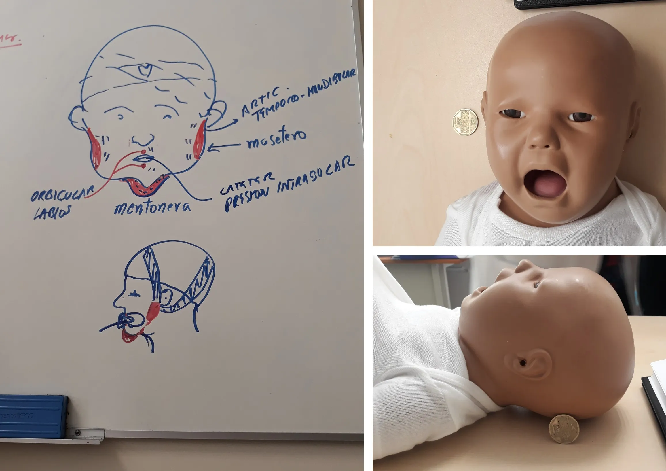
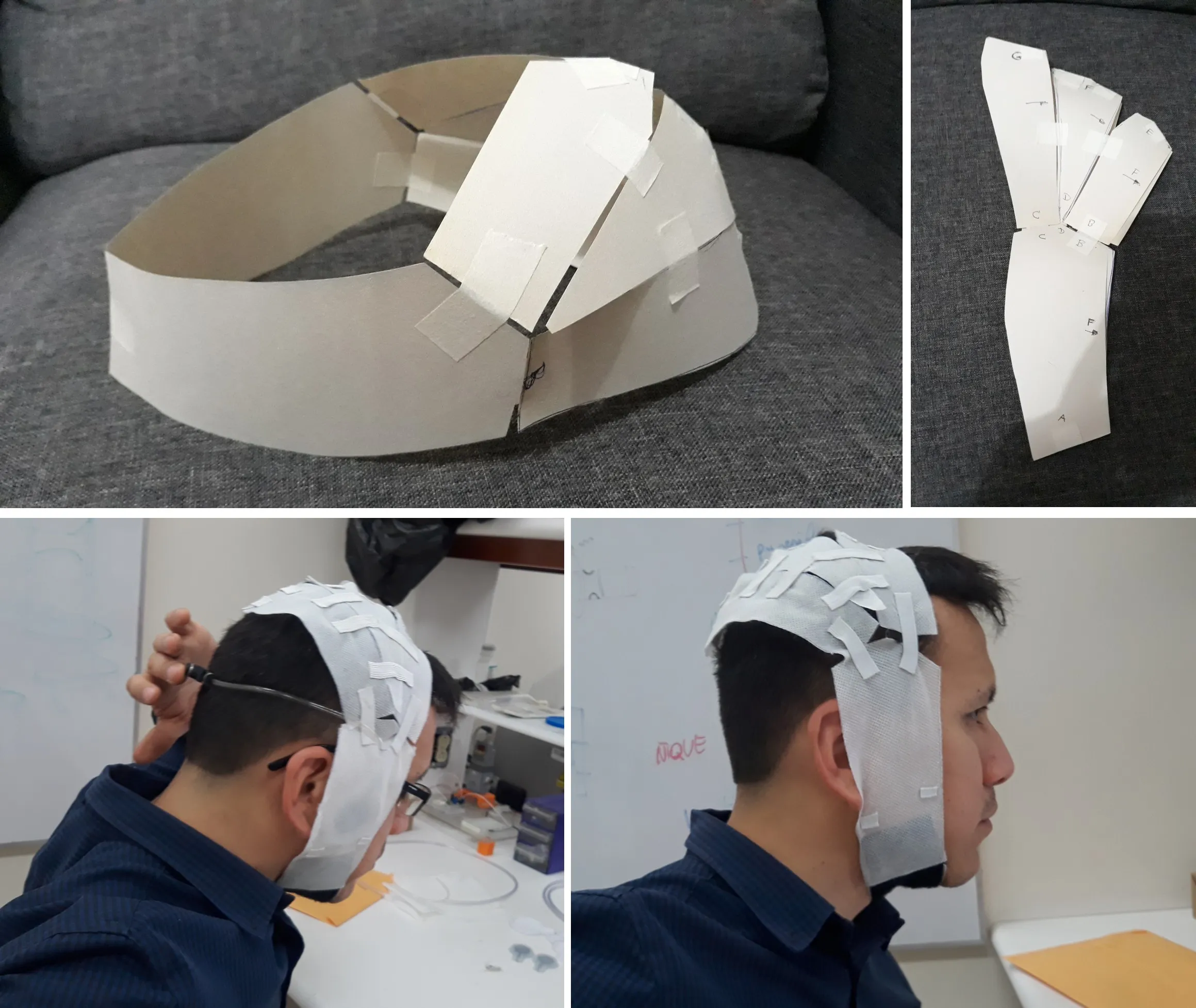
After that, using an approach borrowed from industrial design, I began looking for simple shapes that would provide adequate support for the soft actuators. An initial exploration with a low-fidelity paper prototype made the process easier.
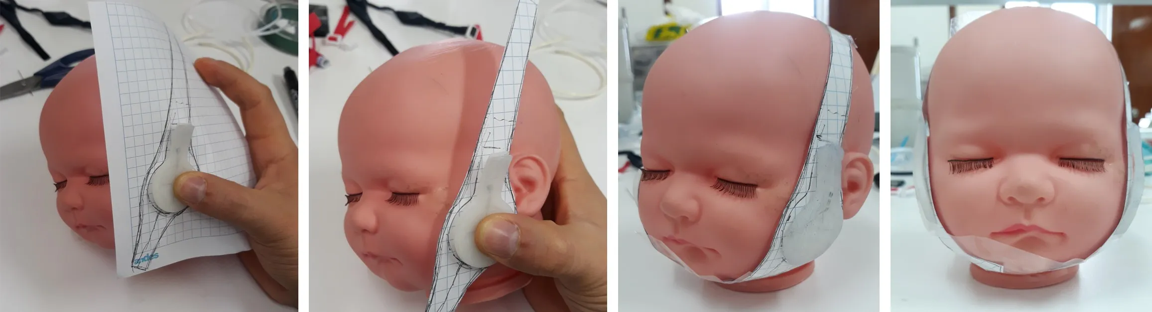
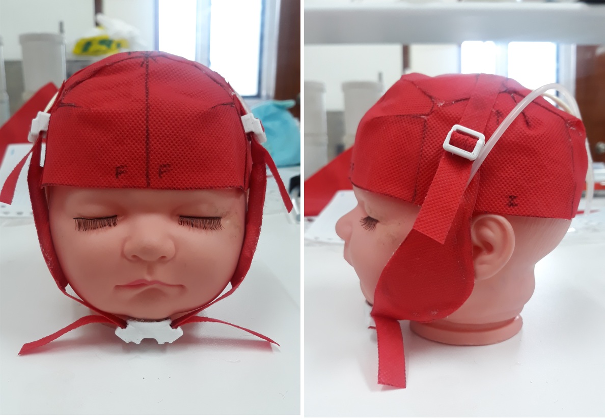
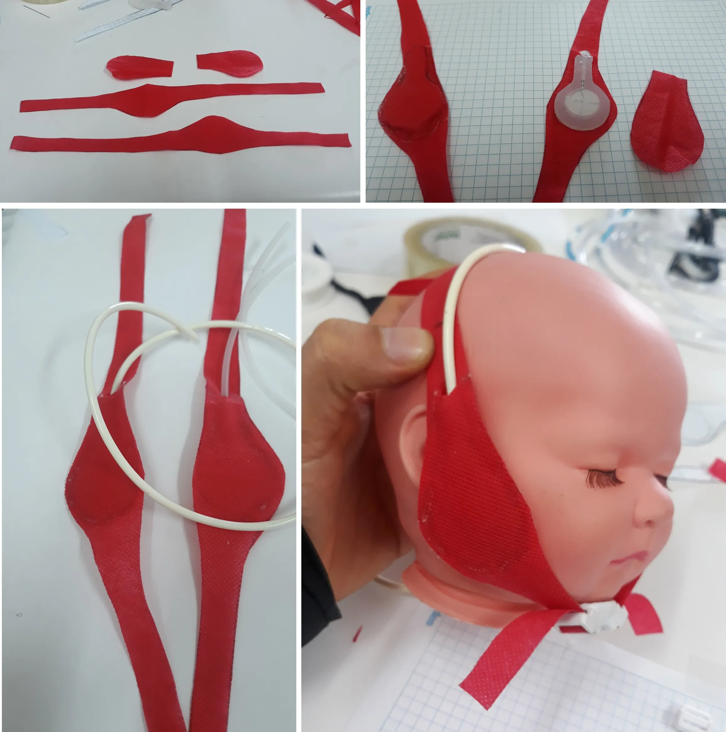
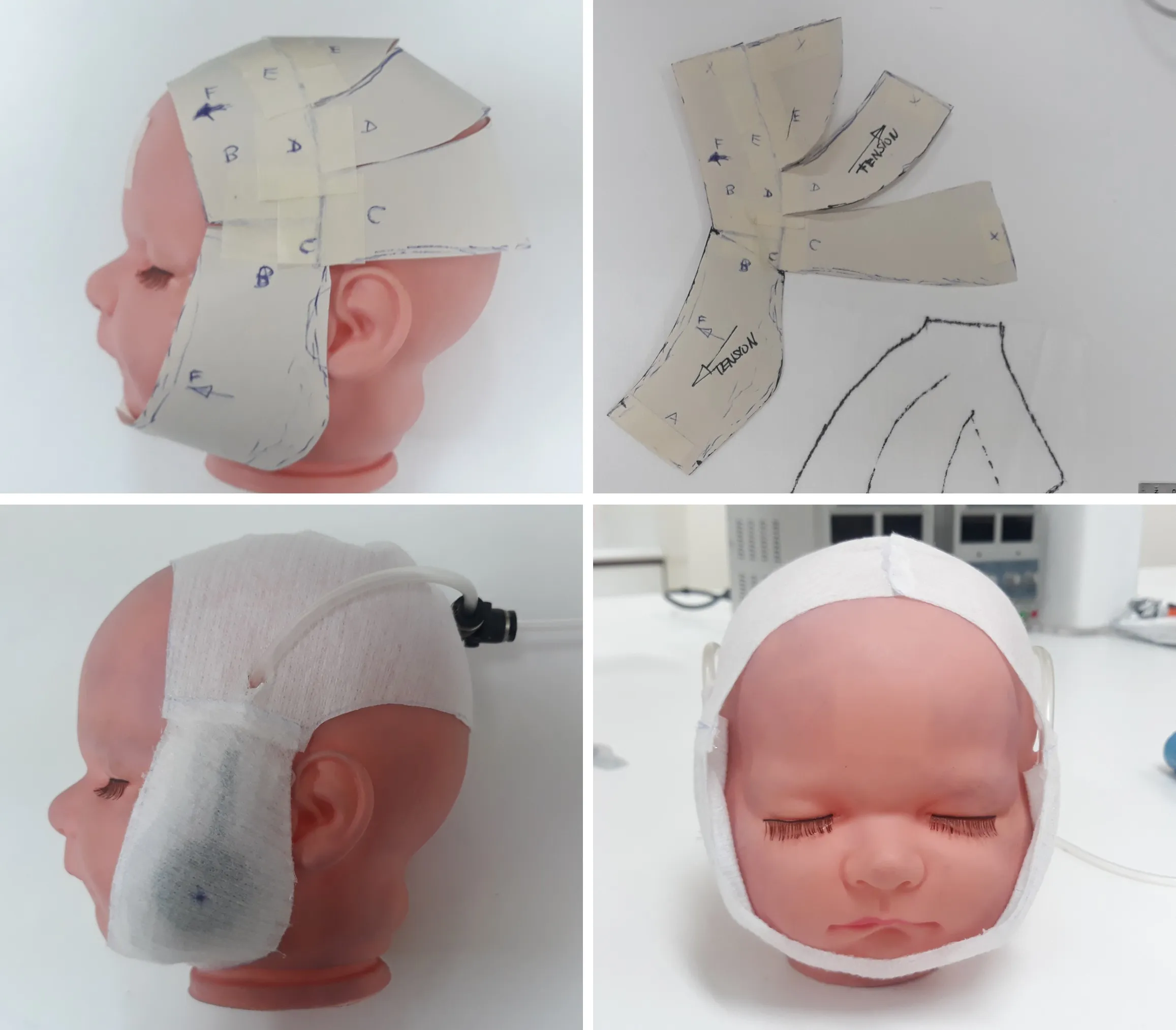
I then used non-woven fabric to produce a first, higher-fidelity prototype. This also allowed me to evaluate the techniques for working with this material. The hands-on learning about how to cut and attach it at this stage was very valuable later on.
At this point, the first prototype was able to hold the actuators and manage reasonably well the cannulas that carry air to them.
Improving the fixation
This prototype helped identify the next challenge. The actuators could be inserted into the device, but the opposite end would not stay in place. So I followed the same low-fidelity paper prototyping method to find a shape that could provide enough fixation without being intrusive for the user.
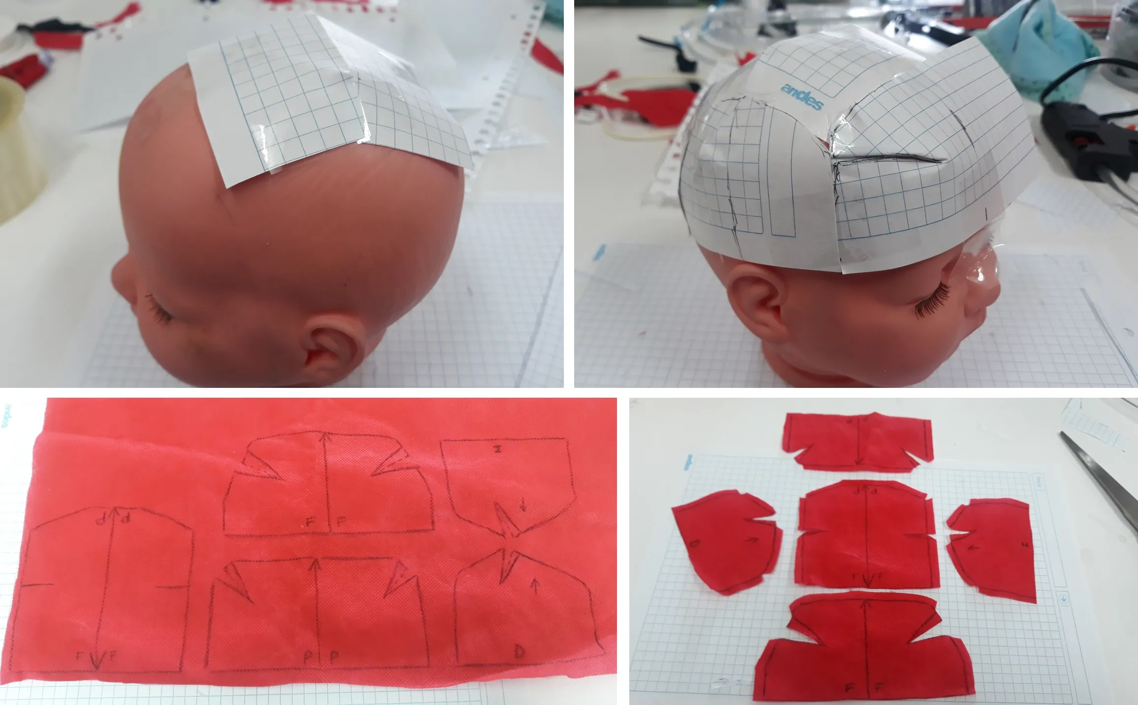
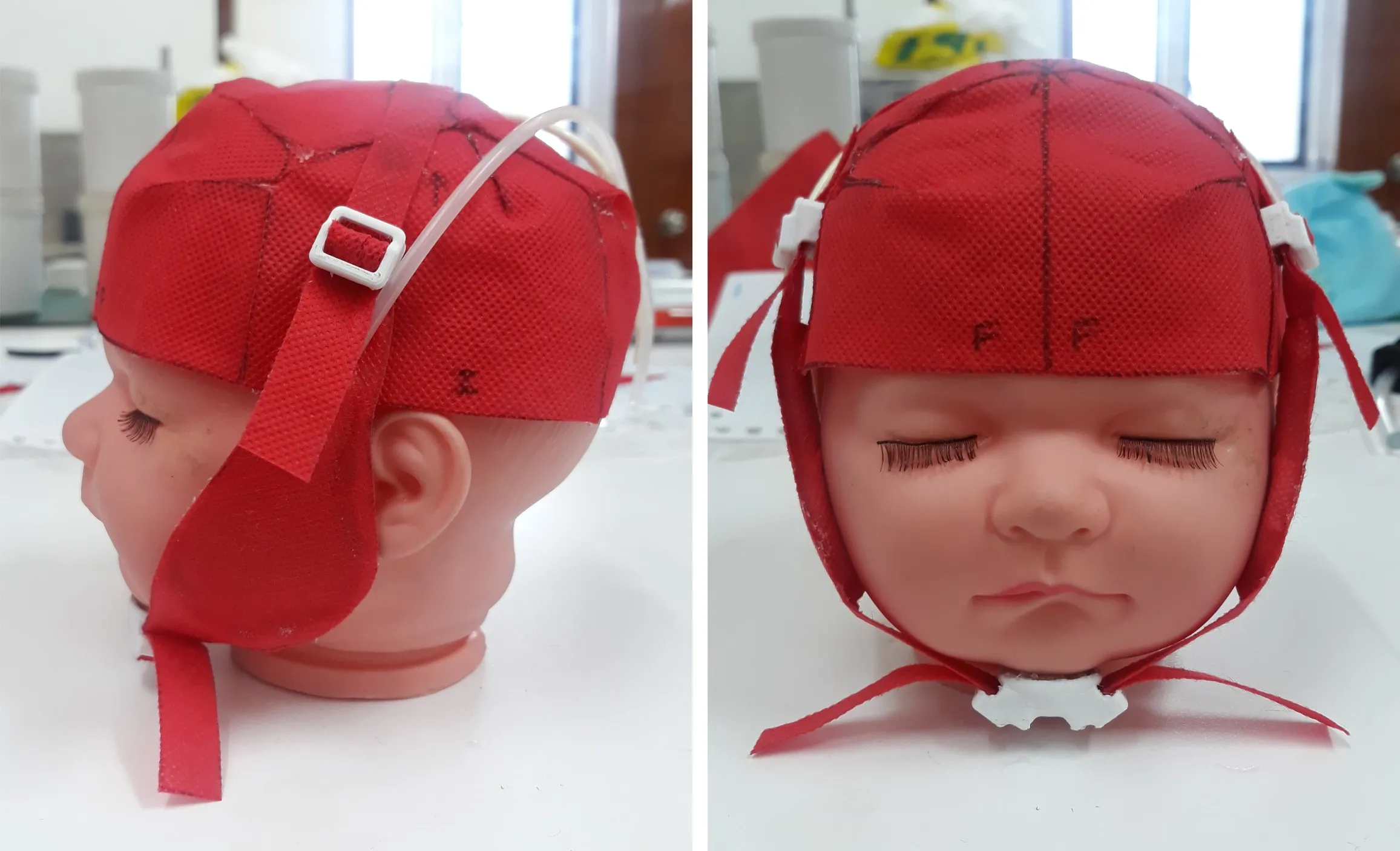
Then I continued with the non-woven fabric to produce the second prototype. Here I included some 3D-printed adjusters (shown in white in the images) that allowed changing the length of the device to improve fixation.
Testing comfort
During this stage, given my industrial-design approach, concern arose about user comfort. The difficulty of this project is that the user is a newborn baby, so it is not possible to run a questionnaire asking how comfortable the device is on a scale of 1 to 5. Because of this, I decided to gather this information directly.
I created an adult-scale version to test the device directly, including larger soft actuators. I tested it myself to assess how much the tension in the device affected comfort and how easy or difficult it was to keep it in place.
With this information, gathered directly and from other team members, I redesigned the device, this time using medical-grade non-woven fabric — the final material.
Characterization of the soft actuators
Another of my goals within the research team was to create a device to measure the force each actuator could exert in relation to the air pressure delivered by the pump. Naturally, this parameter is very important for carrying out proper rehabilitation.
First approach: strain gauges
One of the first approaches I explored for this purpose was the use of strain gauges. In the image below you can see a gauge placed on an acrylic piece, on a cantilevered section, to allow a wider flex that could be measured easily. The gauge needed to exert a force on the cantilevered end of the acrylic piece, applied as centered on the bench as possible.
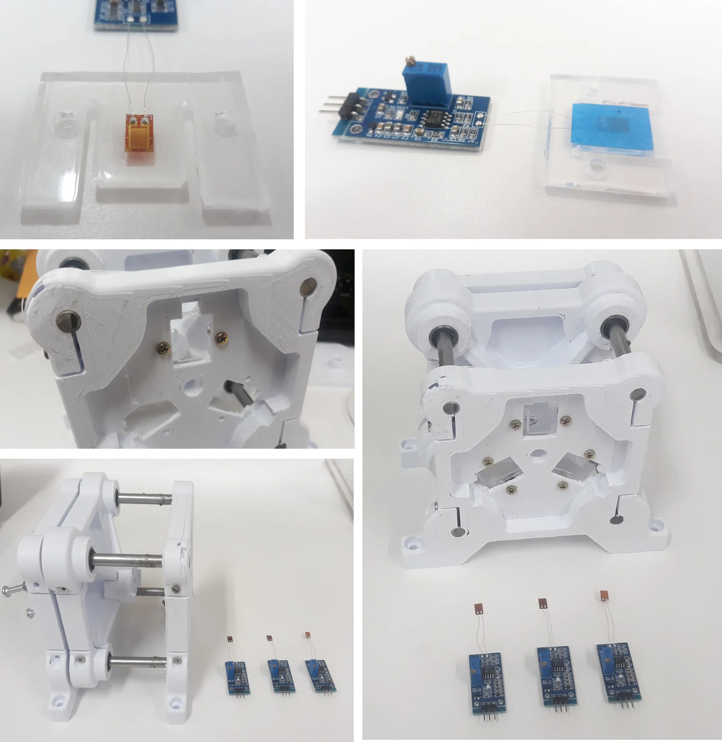
To ensure the forces were parallel, I designed a bench with two fixed panels joined by four smooth steel bars. On these bars I placed a third, sliding panel with linear bearings that traveled along the smooth bars. This sliding panel has an adjustable position, using three bolts, so that the actuators to be characterized could be placed and removed. This way the actuator was placed between a fixed panel, and the sliding panel was positioned to hold the actuator in place. The gauges were placed on the fixed panel in contact with the actuator to read the forces.
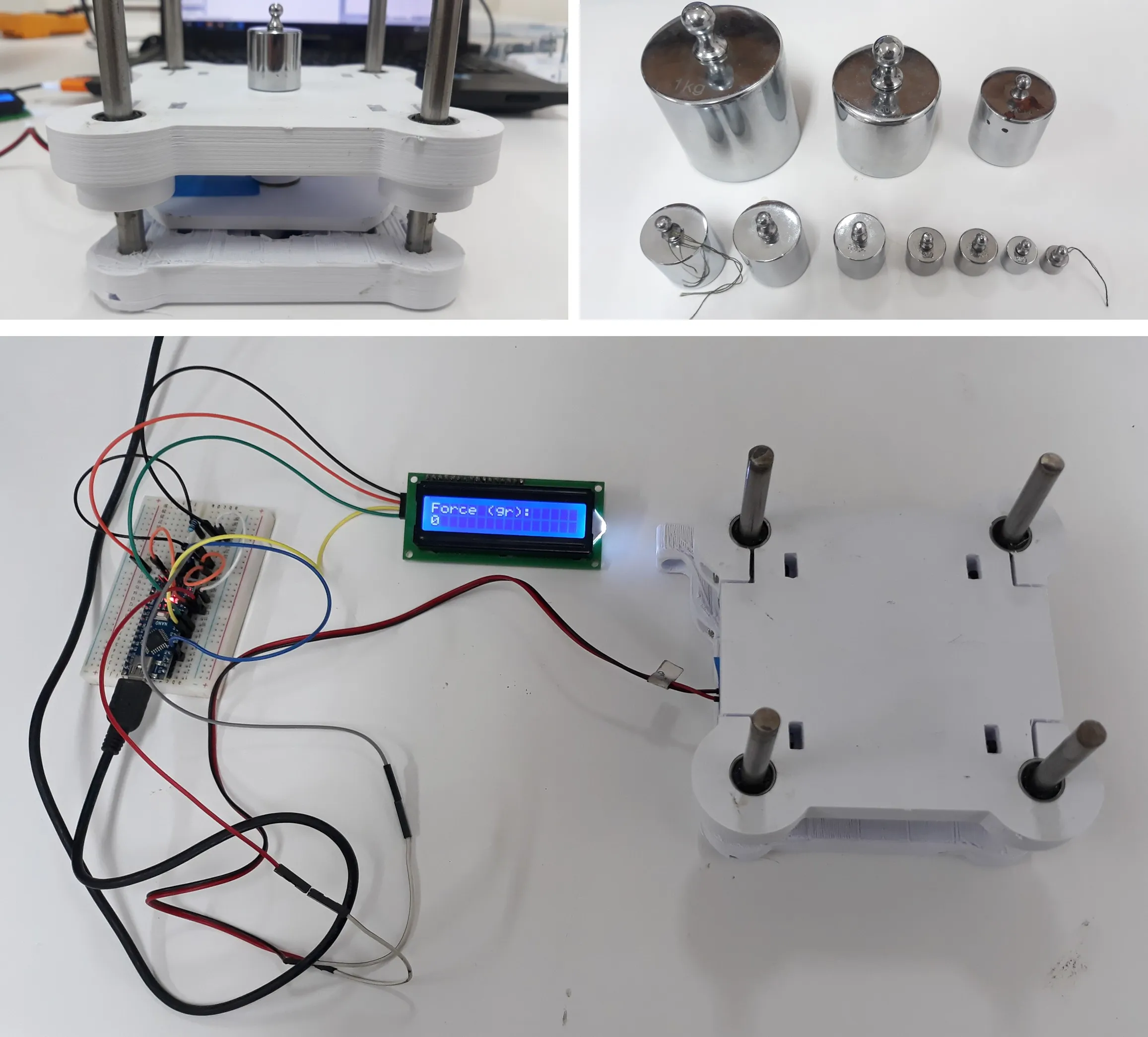
Using weights, the bench was calibrated before being used to measure the force of the actuators. It was at this point that I noticed that, although gauge readings could be obtained, they were only readable over a very narrow range: after a certain point, adding more weight did not increase the gauge flex readings. In other words, the acrylic did not have a suitable reading range.
Switching to an FSR sensor
So I decided to use a more direct setup. I switched to a single Force-Sensing Resistor (FSR) sensor, which showed a reading range better suited to our goal. With this sensor, readings were taken to establish the relationship between air pressure and the force exerted by the soft actuator.
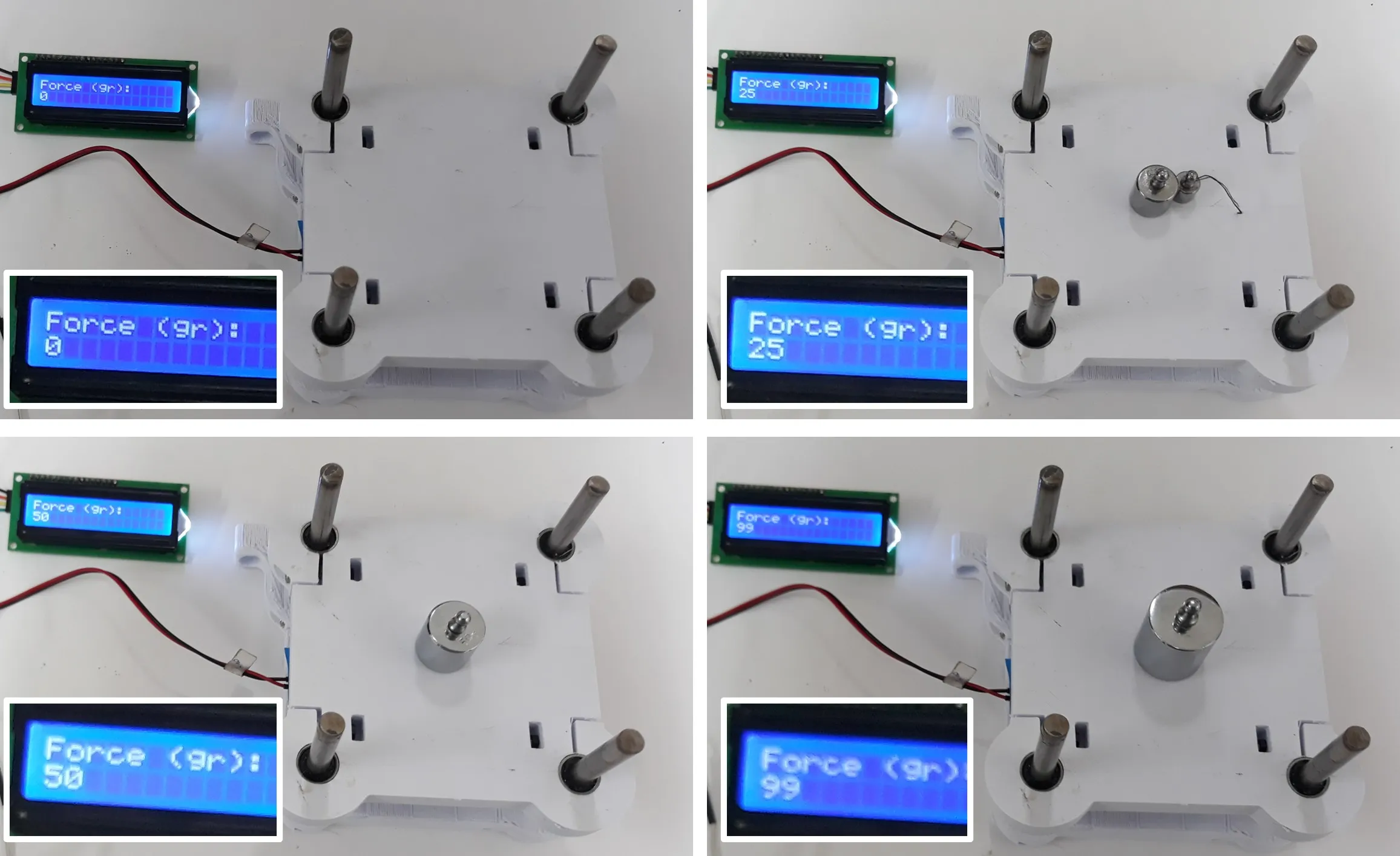
In the image below you can see a soft actuator placed on the characterization bench. The upper fixed panel holds three bolts that adjust the height of the panel that acts as the upper limit for the actuator. Below this limit sits the soft actuator, which, as its chamber expands, presses the lower sliding panel against the fixed panel beneath it. The FSR sensor sits between the sliding panel and the fixed panel.
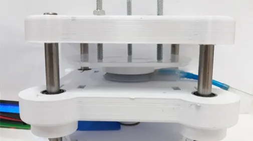
The decision to use a sliding panel comes from the need to apply force to the sensor through the same area in every test. The soft actuator, by its very nature, has a variable contact area as it expands. That is why the sliding panel ensures the sensor reading is taken under similar conditions each time.
Using this bench, we established the relationship between the air pressure supplied and the force it produced, through the reading collected by the FSR sensor.
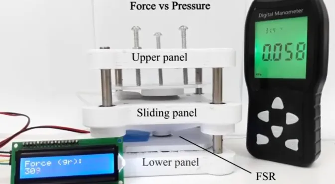
With this work the device prototype was completed, and the biomedical engineering team was able to complement the software development, adding features such as Bluetooth control and data extraction for later verification.